PLC With Drive Panels
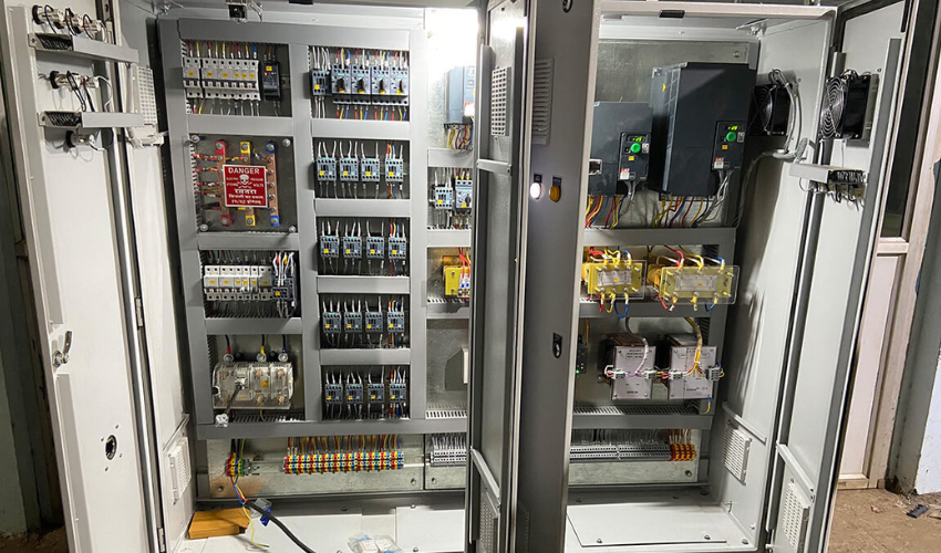
A PLC (Programmable Logic Controller) with Drive Panel integrates
a PLC and a variable frequency drive (VFD) to control the speed,
torque, and operation of motors in industrial applications. These
panels are commonly used in processes such as conveyor systems,
HVAC, pumps, fans, cranes, and elevators, where precise motor
control and automation are essential. The PLC processes signals
and commands the VFD to adjust motor speeds for better
efficiency and performance.
Key Components of PLC with Drive Panels
1. PLC (Programmable Logic Controller)
- Central Processing Unit (CPU) – The brain of the system that processes input
signals and executes the control logic.
- Input/Output Modules – For receiving signals from sensors (inputs) and
controlling actuators (outputs) like solenoids, relays, and motor starters.
- Human Machine Interface (HMI) – Allows operators to interact with the system,view process data and make adjustments.
2. Variable Frequency Drive (VFD)
- Motor Control – VFD adjusts the speed of AC motors by varying the frequency
of the electrical power supplied to the motor.
- Energy Efficiency – Reduces power consumption by ensuring that motors only
operate at the necessary speed for the application.
- Soft Start and Stop – Smooth acceleration and deceleration to reduce
mechanical stress on equipment.
- Protection Features – Includes overload protection, overvoltage, undervoltage and fault detection.
3. Power Supply & Distribution
AC Power Supply – Powers both the PLC and the VFD.
Busbars – Distribute electrical power from the supply to various components in
the panel.
Circuit Breakers/Relays – Protect electrical circuits from faults or overload
conditions.
How PLC with Drive Panels Work
1.Sensors and Inputs
- The PLC receives input signals from sensors (e.g., speed,
temperature, pressure).
- These inputs are processed by the PLC to determine the necessary
adjustments.
2.PLC Control Logic
- Based on the logic programmed in the PLC, the controller processes
the inputs and generates control outputs.
- The PLC sends control commands (e.g., change speed, stop, or start)
to the VFD.
3.VFD Motor Control
- The VFD adjusts the motor speed by varying the frequency and
voltage supplied to the motor.
- It communicates with the PLC to receive real-time adjustments and
feedback.
4.Human Machine Interface (HMI)
- Operators can interact with the system, monitor real-time data, and
manually control the system when necessary.
- The HMI provides a graphical interface to view process parameters,
alarm conditions, and operational status.